
Last Updated on April 10, 2025
If you own a car, you’re likely familiar with OBD (On-Board Diagnostics) scanners. These essential tools provide real-time diagnostic data, allowing car owners and mechanics to monitor engine performance, detect issues, and ensure smooth operation.
At the core of OBD scanners are two critical components: connectors and pinouts. Additionally, each scanner follows a specific communication protocol to facilitate data exchange between the vehicle and the diagnostic tool. One such protocol is the SAE J1850 PWM—a widely used standard in Ford and General Motors vehicles.
In this guide, we’ll explore everything you need to know about the J1850 PWM protocol, including its features, working mechanism, compatibility, and limitations.
What is the SAE J1850 PWM Protocol?
The SAE J1850 PWM (Pulse Width Modulation) protocol is a specialized communication system designed for vehicle diagnostics and data sharing. It is a high-speed protocol that operates at 41.6 Kbps, primarily found in Ford vehicles.
This protocol is classified as a Class-B system, meaning it can transmit parametric data between multiple nodes, reducing the need for redundant sensors in the vehicle’s electronic system.
SAE J1850 PWM OBD2 Protocol Specifications
| Feature | Description |
|---|---|
| Bus State | Active when BUS + is pulled HIGH and BUS – is pulled LOW |
| Data Transmission Rate | 41.6 Kbps |
| Number of Bytes per Message | 12 |
| Bit Timing | ‘1’ bit – 8μs, ‘0’ bit – 16μs, Start of Frame – 48μs |
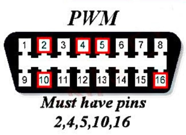
| Ground (GND) Pins | Pins 4, 5 |
| Power Supply (12V) | Pin 16 |
| BUS + (Positive Signal) | Pin 2 |
| BUS – (Negative Signal) | Pin 10 |
| Maximum Signal Voltage | 5V |
| Minimum Signal Voltage | 0V |
How Does the SAE J1850 PWM Protocol Work?
The J1850 PWM protocol works by modulating pulse width to transmit digital data across a two-wire system. This allows vehicles to send and receive diagnostic information between different ECU (Electronic Control Unit) modules.
Here’s a step-by-step breakdown of how this protocol functions:
- Data Transmission: The protocol uses pulse width modulation (PWM), meaning it encodes data by varying the width of electrical pulses.
- Dual-Wire Communication: It operates on a two-wire system (BUS + and BUS -), ensuring a more reliable signal.
- Class-B Protocol: It enables parametric data sharing, reducing the need for multiple sensors.
- Voltage Regulation: Operates between 0V (Low) and 5V (High) for data interpretation.
- Active State Functionality: The BUS + is high, and BUS – is low when the system is active.
Why Did Ford Use the J1850 PWM Protocol?
Ford adopted the J1850 protocol because of its efficient power regulation and ability to handle high-speed data transmission. The pulse width modulation (PWM) method enables:
✔ Better power management – Reduces average power consumption using an electrical signaling system.
✔ Efficient data transmission – Eliminates redundant sensors by sharing data between ECUs.
✔ Reliable vehicle diagnostics – Allows real-time troubleshooting of vehicle performance.
However, one disadvantage of this system is its variable pulse width, which affects the power distribution. If the transmission power is too high, it may lead to unstable performance, reducing efficiency compared to newer OBD-II protocols like CAN (Controller Area Network).
J1850 PWM Compatibility & Supported Vehicles
Not all vehicles use the J1850 protocol. This system is primarily found in:
- Ford vehicles (manufactured between 1996 and the early 2000s)
- Some General Motors (GM) models
- Older OBD-II compliant vehicles before the transition to CAN bus
Before purchasing an OBD-II scanner, ensure it supports J1850 PWM, as not all scanners are compatible with this protocol.
OBD-II Scanners & Apps That Support SAE J1850 PWM
Many modern OBD-II scanners and mobile apps can interpret the J1850 PWM via Bluetooth or Wi-Fi adapters. Popular apps that support this protocol include:
✅ Torque Pro (Android)
✅ OBD Car Doctor (Android & iOS)
✅ Car Scanner ELM OBD2 (Android & iOS)
These apps allow users to:
- Read and clear diagnostic trouble codes (DTCs)
- Monitor real-time vehicle data
- Check engine performance
Final Thoughts: Is the J1850 PWM OBD2 Protocol Still Relevant?
While SAE J1850 PWM was once a dominant protocol for vehicle diagnostics, modern cars now use more advanced OBD-II protocols like CAN bus for faster, more efficient communication.
However, if you own an older Ford or GM vehicle, understanding J1850 PWM is essential for accurate diagnostics and maintenance. Be sure to use a compatible scanner and OBD-II app to access real-time vehicle data.
FAQs
1. What is the J1850 PWM Protocol?
The J1850 PWM (Pulse Width Modulation) protocol is a vehicle communication standard used in OBD-II systems, primarily in Ford and General Motors vehicles, to enable data exchange between the vehicle’s ECUs and diagnostic tools.
2. Which vehicles use the J1850 protocol?
The J1850 PWM protocol is commonly found in Ford vehicles (1996–early 2000s) and some General Motors models before transitioning to newer protocols.
3. How does J1850 PWM differ from other OBD-II protocols?
Unlike protocols like ISO 9141-2 or CAN bus, J1850 PWM operates on a higher-speed, two-wire system using pulse width modulation for data transmission, making it faster than older protocols but less efficient than CAN.
4. Can all OBD-II scanners read the J1850 PWM protocol?
No, not all OBD-II scanners support J1850 PWM. Check your scanner’s specifications to ensure it is compatible with this protocol before purchasing.
5. Is the J1850 PWM protocol still in use today?
No, most modern vehicles (post-2008) have switched to the CAN bus protocol, which offers higher efficiency and faster data transfer rates. However, J1850 PWM is still relevant for diagnosing older Ford and GM vehicles.